Solar Pro Magazine Showcases Cenergy's Indianapolis Airport Phase I Project

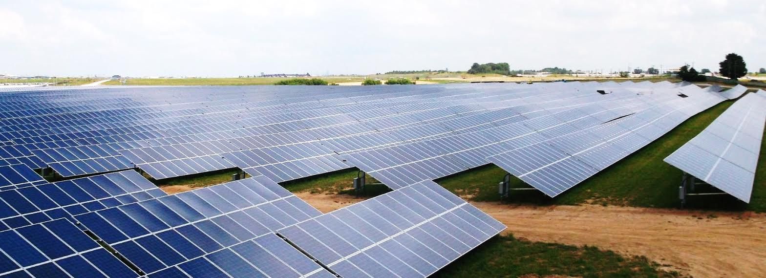
The 10 MWac Indianapolis Airport Phase I (Indy I) solar farm was commissioned in September 2013. The largest solar farm located on an airport site in the US, Indy I covers 75 acres of Indianapolis Airport property. Indianapolis Power & Light (IPL) is purchasing the solar energy that Indy I produces from General Energy Solutions USA (GES USA) via a 15-year power purchase agreement.
In addition to GES USA, the Indy I project team included Telamon, Johnson Melloh Solutions and Cenergy Power. The project created 140 temporary jobs during the construction phase, as well as 12 permanent O&M positions.
Cenergy Power and Solectria Renewables worked closely together to develop the optimal power conditioning and ac collection systems for the site. Indy I has a 1.25 dc-to-ac ratio. The power conditioning system includes 20 Solectria SGI-500XT inverters deployed on seven 1 MW and two 1.5 MW inverter pads. Nine 1,000 kVA 3-winding Cooper transformers with a 208 V Delta to 13.8 kV wye-grounded configuration are each connected to two 500 kVA Solectria inverters. Each of the remaining two 500 kVA Solectria inverters has a corresponding 2-winding transformer with a 208 V Delta to 13.8 kV wye-grounded configuration.
The ac collection system includes two radial 5 MW daisy-chained feeders connected to 15 kV IEM switchgear. The switchgear has two 15 kV load-break interrupting switches that are manually operated for each feeder. The two 5 MW feeders are combined inside the switchgear and go to a 15 kV main draw-out circuit breaker equipped with two SEL 351S-7 relays for protection and control. One SEL 735 revenue meter monitors system output at the switchgear and is connected to a Draker SCADA unit.
Utility metering is accomplished through a pad-mounted 15 kV S&C Electric Company metering unit linked to the IPL remote terminal unit via radio communication. A pad-mounted 15 kW G&W Viper-ST recloser and a riser pole with a 15 kV pole-mounted gang-operated air-break switch provide interconnection to the IPL 13.8 kV line.
Cenergy was able to successfully complete the Indianapolis Airport solar project ahead of schedule and below budget in great part due to the supportive efforts of municipal, airport and utility officials within the city of Indianapolis.- Bill Pham, CEO, Cenergy Power
Overview
OWNER/DEVELOPER: General Energy Solutions USA
CO-DEVELOPERS: Telamon, Johnson Melloh Solutions
PROJECT EPC: Cenergy Power
DATE COMMISSIONED: September 2013
INSTALLATION TIME FRAME: Approximately 160 days
LOCATION: Indianapolis, IN, 39.7°N
SOLAR RESOURCE: 4.6 kWh/m2/day
ASHRAE DESIGN TEMPERATURES: 89.6°F 2% average high, -7.6°F extreme minimum
ARRAY CAPACITY: 12.569 MWdc
ANNUAL AC PRODUCTION: 17,057 MWh
Equipment Specifications
MODULES: 44,128 total; 19,800 General Energy Solutions (GES) 7C00-6C295, 295 W STC, +5/-0 W, 8.32 Imp, 35.47 Vmp, 8.95 Isc, 46.20 Voc; 17,776 GES 7C00-6C290, 290 W STC, +5/-0 W, 8.19 Imp, 35.40 Vmp, 8.82 Isc, 45.5 Voc; 6,552 Sharp ND-240QCJ, 240 W STC, +5/-0%, 8.19 Imp, 29.3 Vmp, 8.75 Isc, 37.5 Voc
INVERTERS: 20 Solectria Renewables SGI-500XT, 500 kW rated output, 600 Vdc maximum input, 300–500 Vdc MPPT range, external transformer, 3-phase 208 Vac output; 13.8 kV point-of-utility connection
ARRAY: 20 subarrays; GES modules: 11 modules per source circuit (GES 7C00-6C295: 3,245 W, 8.32 Imp, 390.2 Vmp, 8.95 Isc, 508.2 Voc), 3,416 GES source circuits total, 12–16 combiners per inverter terminated at inverter-integrated 600 Vdc breakers; Sharp modules: 13 modules per source circuit (3,120 W, 8.19 Imp, 380.9 Vmp, 8.75 Isc, 487.5 Voc), 504 Sharp source circuits total, 12–16 combiners per inverter terminated at inverter-integrated 600 Vdc breakers; 12.569 MWdc array capacity total
ARRAY INSTALLATION: Ground mount, Schletter FS System racking, 180° azimuth, 25° tilt
SOURCE CIRCUIT COMBINERS: 299 SolarBOS, models CS-06-15-N3, CS-08-15-N3, CS-10-15-N3, CS-12-15-N3 and CS-14-15-N3
SYSTEM MONITORING: Draker PV 2000 with environmental monitoring, cellular modem at the switchgear pad, and wireless network switch and media converter at each inverter pad